Cn3D macromolecular structure viewer


Structure Alignments in Cn3D

  Retrieving structure alignments (VAST)  
 

While Cn3D does fine with single structures, it's even better suited to displaying structure alignments of multiple proteins. NCBI creates and maintains a database of such alignments, called VAST, for all pairs of proteins from MMDB whose structures have some similar core regions. VAST does two things for each related pair: it calculates an optimal 3-d superposition for the conserved core, and constructs a sequence alignment based on the correlation of the 3-d structures.


Cn3D is the primary visualization tool for VAST alignments. Its combination of structure and sequence displays allow the VAST user to view both the structure alignment and the sequence alignment created from it, with color schemes that denote and emphasize the conserved regions.


Let's take a look at the PTEN structure and its VAST neighbors. Go to the VAST homepage, type "1D5R" in the query box and hit "Get." This brings up the familiar MMDB summary page. The graphic is saying that the protein is composed of a single chain (A) that NCBI has parsed into two domains: the N-terminal domain 1, and C-terminal 2. Clicking on the top bar marked "Chain A" will bring up VAST neighbors based on the whole chain, while clicking on the colored regions marked "1" or "2" will show neighbors of these individual domains.


Click on the "1" domain to bring up the neighbor list for the N-terminal domain. The PTEN structure paper (Lee et al., 1999) emphasizes the similarities between PTEN and dual specificity phosphatase (1VHR in the PDB). Select the checkbox to the left of 1VHR chain A, then hit "View 3D Structure" to bring up this VAST alignment in Cn3D. We'll use it as the example for the following section.


  Viewing structure alignments in Cn3D back to top
 

As described in the previous paragraph, load in the VAST alignment of 1D5R and 1VHR. The default view when Cn3D first starts up is of two proteins superimposed and drawn with virtual backbones (straight cylinders connecting alpha carbons), by which the close overlap of alpha carbons in the aligned core regions is emphasized.


The default coloring for structure alignments in Cn3D uses red and blue for the regions aligned by the VAST algorithm, where identical aligned residues are red, and different but aligned residues are blue; unaligned regions are colored gray. Note that because of the way VAST works, the aligned regions tend to correspond to individual or groups of consecutive secondary structure elements - helices and strands, while the loops outside the core vary in length and orientation and are often left unaligned. The structures' colors are reflected in the sequence display, discussed in more detail below.


The initial style and color settings for structure alignments are equivalent to the combination of the Style:Rendering Shortcuts:Tubes and Style:Coloring Shortcuts:Sequence Conservation:Identity menu options. The drawing settings for structure alignments are user-adjustable in the same way as single structures. For example, here is a Cn3D reproduction of figure 2A in the PTEN structure paper (Lee et al., 1999), with the same basic drawing style and view orientation. The figure clearly shows the close structural relationship between the two proteins, as the orientations and positions of the major secondary structure elements are quite similar. But the loops around the active site, here occupied by inhibitors, vary greatly in size and position in order to accommodate different substrates.


... and click here to launch this figure in Cn3D


  Cn3D's alignment viewer back to top
 

Cn3D's sequence window also functions as an alignment viewer when displaying more than one structure or a structure to which multiple sequences have been aligned..


The alignment display is fairly straightforward. There is one row for each sequence, with the master sequence always on top. Only sequences that are part of the alignment are shown, even if a structure has multiple chains. As always, each letter in the sequence takes on the color of the corresponding alpha carbon (or phosphate) in the structure. Highlights are also shared between sequence and structure windows.


However, there are some important differences between structure-based alignments in Cn3D and sequence alignments from common algorithms like BLAST or ClustalW, both in the display and the underlying alignment data. This is the subject of the next section.


  Cn3D's alignment model back to top
 

The first questions the new user might ask when viewing a VAST alignment in Cn3D are, "Why are some letters uppercase and others lowercase? And what are these funny '~' characters?" The short answer is that aligned residues are displayed in capital letters, unaligned in lowercase, and the '~' represents an unaligned gap. But the latter, especially, requires a bit more explanation.


Dynamic programming sequence alignment algorithms align residues based on a mutation probability score, and use gaps to model evolutionary insertions or deletions in one sequence with respect to another. An inserted residue is aligned with gap in the algorithm's bookkeeping, and is scored accordingly (a gap penalty). These aligned gaps are customarily drawn as a '-' (dash) character. This allows a continuous gapped alignment to cover a large region of two sequences, even when there are significant evolutionary differences between them.


In a structure alignment (e.g. from VAST), one residue is aligned with another because their alpha carbons are nearby in space. Hence, the notion of a residue being "aligned to a gap" has no physical meaning, because an alpha carbon in one structure cannot correspond to empty space in another. Instead, the alignment is made discontinuous: aligned regions - helices or strands that overlap closely and continuously between two structures - are separated by unaligned regions, which are typically loops with sufficiently different lengths and orientations that they cannot be meaningfully superimposed.


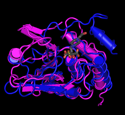
Take for example the alignment of 1D5R and 1VHR, as discussed above.


The first two blocks have been highlighted in these screen shots, showing that the first corresponds to a beta hairpin in the structure, and the second to a helix. As can be seen from the structure, these are separated by a long loop in 1D5R, but by only a short one in 1VHR.


Showing the unaligned residues inbetween the blocks, while keeping the aligned residues correctly on top of one another, requires some allowance to be made for different loop lengths. This is accomplished by using '~' characters to fill out a shorter unaligned stretch - they are gaps in the display only, and do not come from nor imply anything about the underlying alignment. Hence the shorter loop area of 1VHR is padded out with '~' characters, so that the longer loop of 1D5R has room to be displayed.


The default display for alignments has the Unaligned Justification:Split style. This shows residues from a shorter unaligned region split in the middle and put adjacent to the aligned blocks on either side. This is perfectly equivalent to the Unaligned Justification:Center option, which places unaligned residues in the center of the space between aligned blocks. These two styles are depicted below.


... "split" unaligned (default)


... vs. "centered" unaligned


The difference between the two is slight, but illustrates a very important point: that the unaligned residues are displayed as a convenience to the user, but nothing can nor should be inferred from the apparent "alignment" of residues in the unaligned areas (e.g., lower case letters). This contrasts directly with gapped dynamic programming alignments, where the number, length, and position of the gaps affect the score. The two displays above would score very differently if interpreted as gapped continuous alignments.


Another important issue is how Cn3D creates what looks like a multiple alignment when more than two structures are viewed, out of what is actually a series of master/slave pairs. This is discussed separately in a page about the "intersect by master" algorithm.


Revised 20 September 2016